Turning your car might feel effortless, but behind the scenes, a complex system of parts work together to make that motion possible. In this article we will go over those parts and dive into how they unite to effortlessly turn a car.
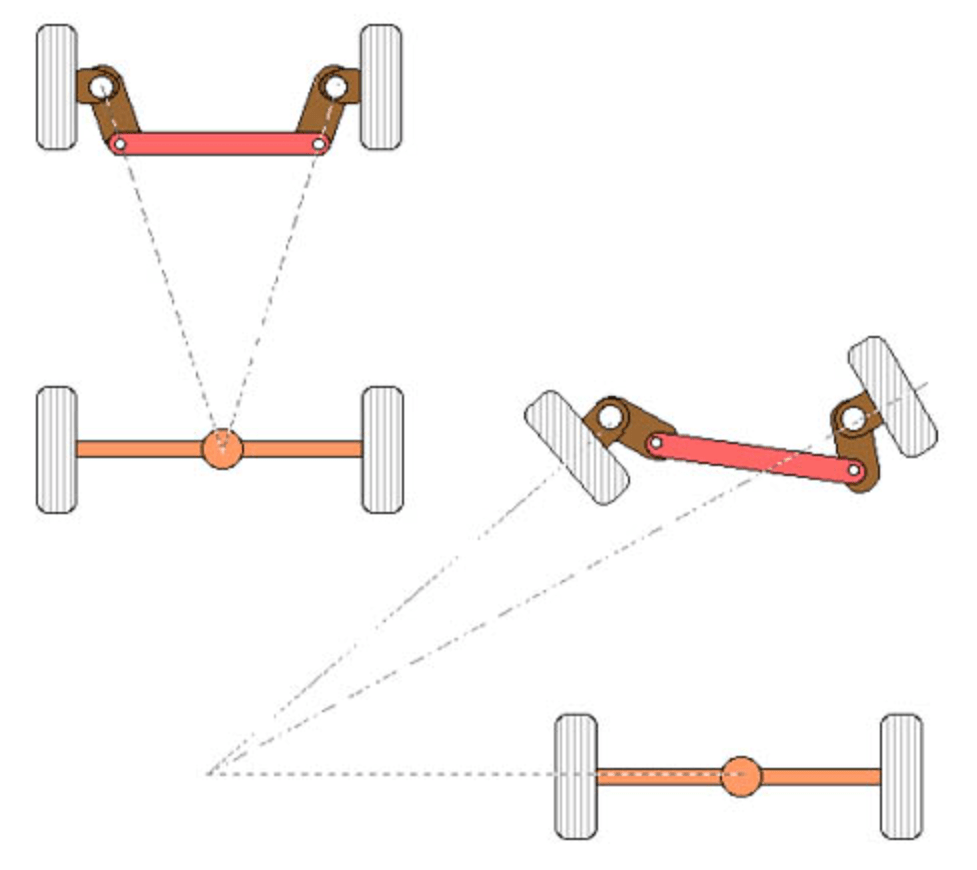
To start, we will go over basic steering principles and geometry to build a foundation on the concept of steering. Cars use Ackermann Steering Geometry when they turn. This means the inside wheel of the car turns at a greater angle than the outside wheel. The purpose of this is to ensure that both wheels have the same axis of rotation, helping to prevent your car from skidding.
With that context, let’s examine each component in the steering system and follow the path from driver input to wheel movement.
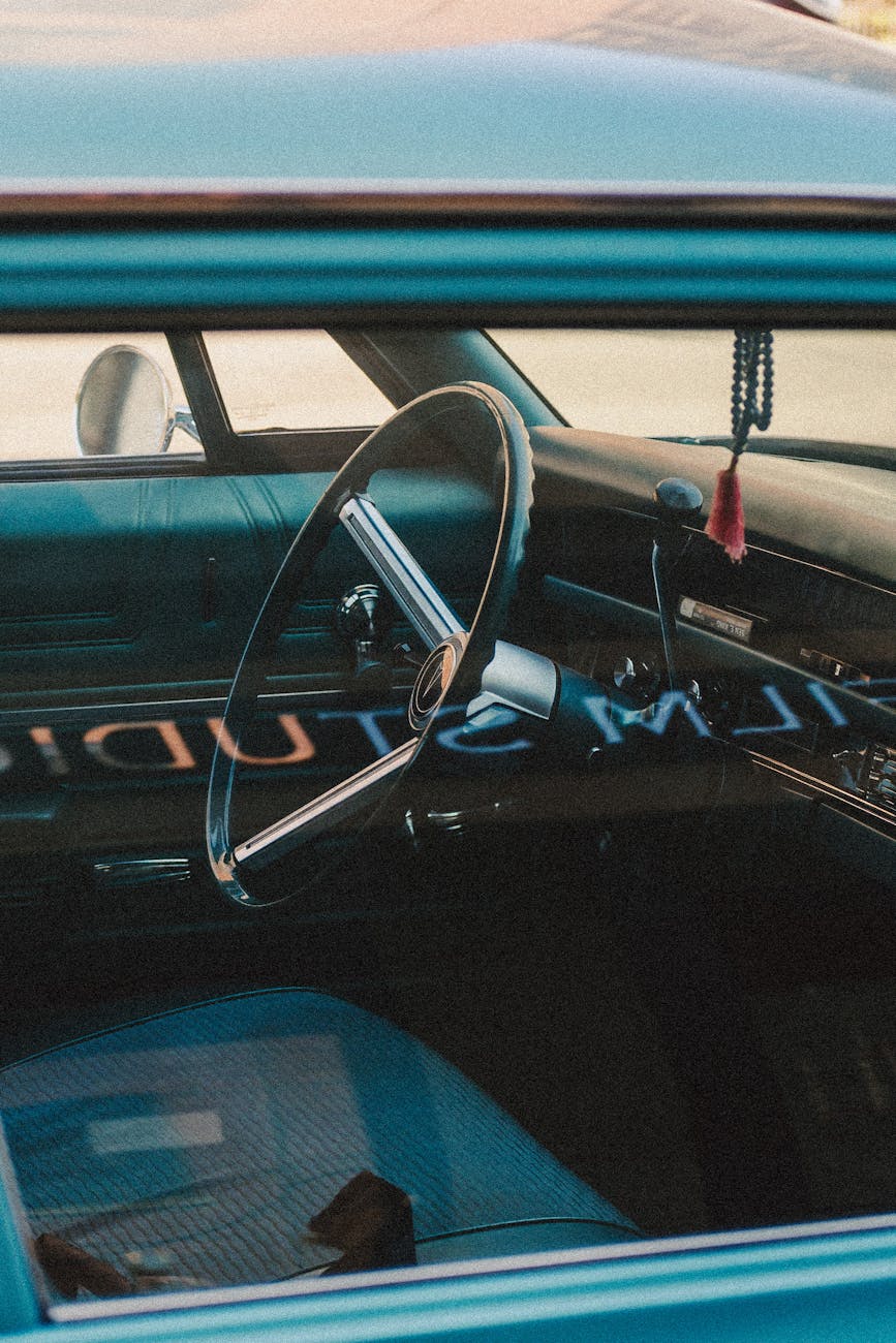
Steering Wheel
This is the face of your car’s steering system, it’s how the driver controls the wheels. Typically, there is an airbag inside the steering wheel and it’s where the horn on your car is located.
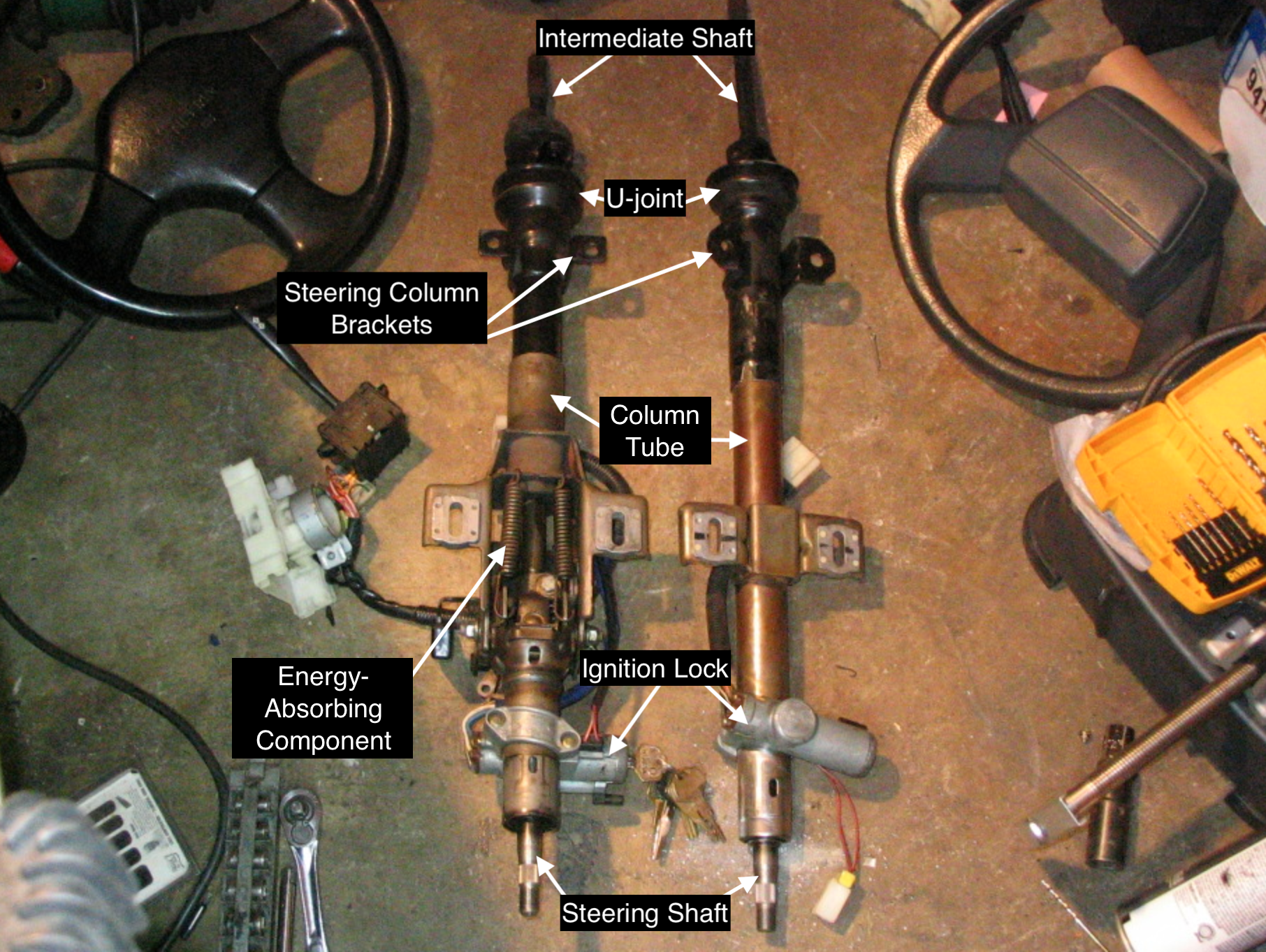
Steering Column
The steering column is a metal tube that connects the steering wheel to the rest of the steering system. It is usually made of steel, aluminum, or magnesium. The steering column itself has multiple subcomponents:
Steering Shaft
The steering shaft is a rod that physically transmits torque from the steering wheel into the rest of the steering gear. It is usually connected to the steering column using a universal joint.
Universal Joints
Universal joints (U-Joint) allow two shafts to join together at an angle while still allowing for rotation. Some steering shafts have a universal joint located on the column tube at the end which allows the steering wheel to be moved up and down.
Column Tube
The column tube houses the steering shaft and provides structural support.
Mounting Brackets
Mounting brackets secure the steering column to the vehicle chassis.
Locking Mechanisms
Locking mechanisms prevent steering without the correct key by interfering with the steering shaft’s motion via a pin located in the ignition lock.
Energy-Absorbing Components
Energy-absorbing components are designed to collapse in a controlled manner during a collision to protect the driver.
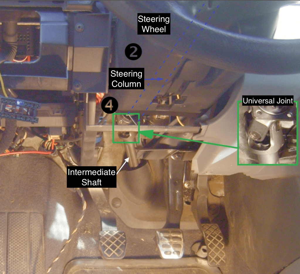
Intermediate Shaft
If the steering shaft needs to change location (due to the placement of the steering system), a pair of universal joints (U-joints) and a short intermediate shaft connect the main shaft (via a universal joint) to the steering gear. See the image below for an example of why an intermediate shaft is sometimes necessary.
Steering Gearbox:
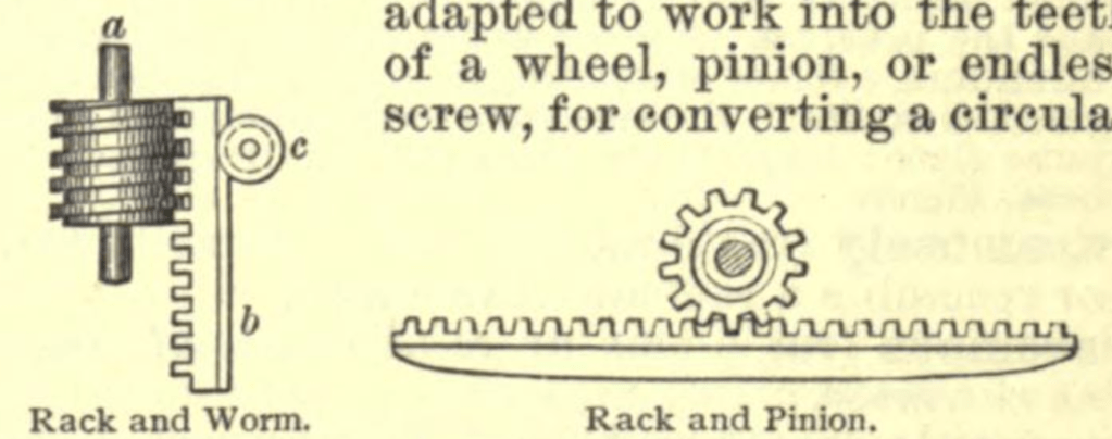
A steering gearbox turns the rotational motion of turning a steering wheel into the translational motion of changing the angle of the wheels. This can be done through several different methods but we will go over the two most common for now.
The first is the rack and pinion method which involves using a circular gear on the end of the steering shaft to make a linear rack move side to side. This linear rack is connected to the wheels and changes the angle of them as they move side to side.
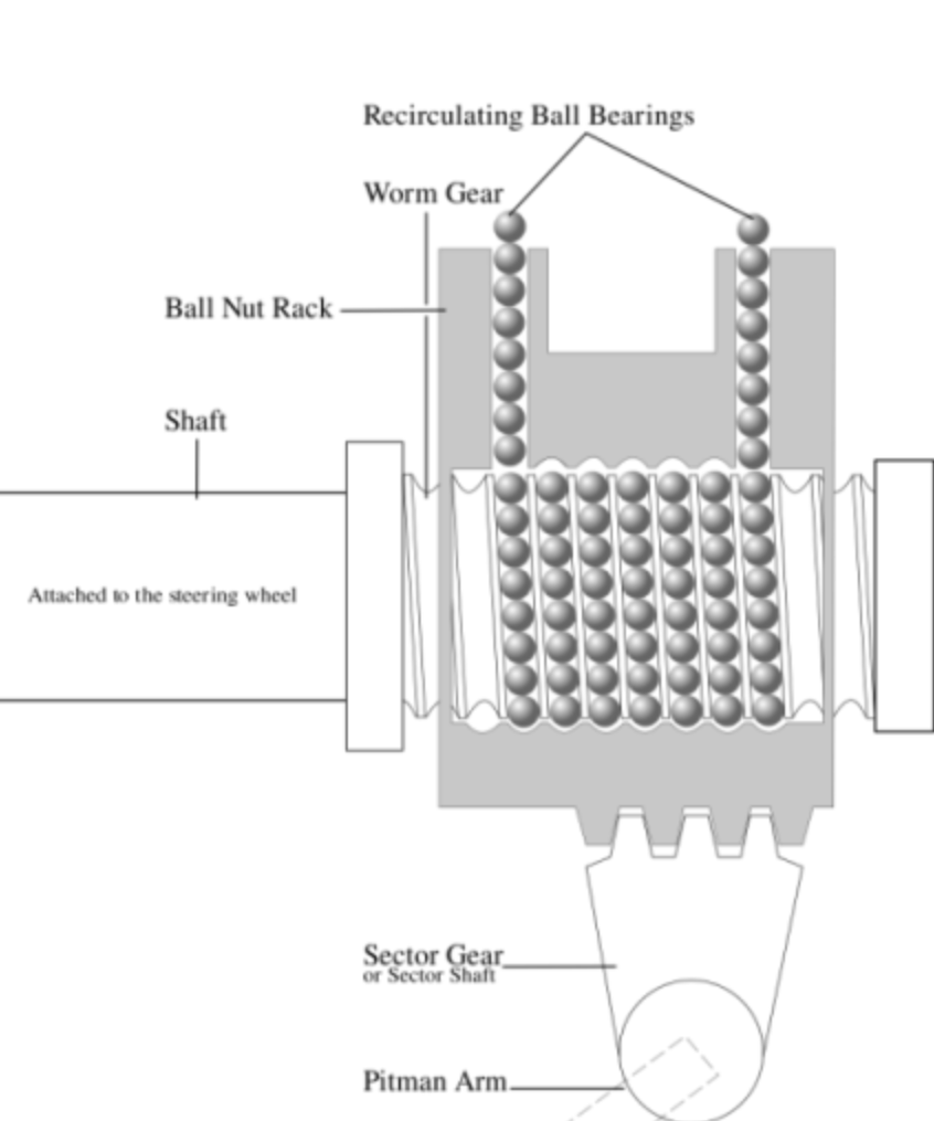
The second method is the recirculating ball steering system. It is a traditional method used in many trucks and older vehicles.
When the steering wheel is turned, the steering shaft rotates a worm gear inside the steering box. Wrapped around this worm gear is a ball nut (also called a rack piston), which is filled with ball bearings. These ball bearings roll between the worm gear and the ball nut, reducing friction and allowing smooth movement. As the worm gear turns, the ball nut moves along it.
Attached to the ball nut is a sector gear, which rotates with the nut’s motion. This sector gear is connected to a pitman arm, which swings left or right depending on your steering input. The pitman arm then moves the steering linkage, which includes the drag link, tie rods, and finally the steering knuckle, turning the front wheels.
Tie Rods
Tie rods connect steering gear (like a rack) to the steering knuckle, this is the last step in converting the driver’s rotational motion into a translational one. Usually tie rods consist of an inner tie rod and an outer tie rod end.
The inner tie rod is connected to the steering rack and moves in and out as the rack moves side to side. It is usually protected by a rubber bellow or boot to ensure that dirt and grease don’t interfere with its function.
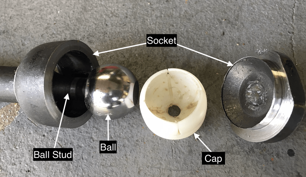
Outer tie rod ends connect to the steering knuckle via a ball joint. This allows the wheel to move during turning while still allowing suspension movement. The outer tie rod end also includes a tapered stud that fits into the knuckle and is secured with a castle nut and cotter pin.
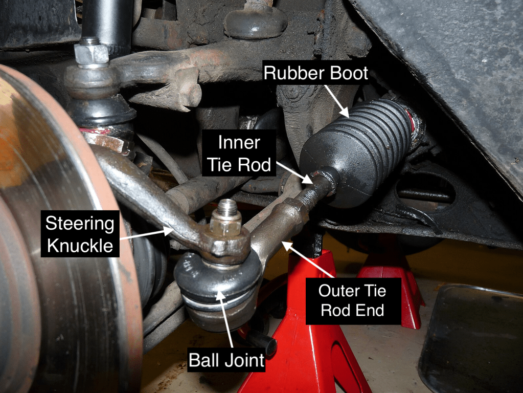
Each tie rod end is connected to a steering knuckle, which is the pivoting part that holds the wheel hub. As the tie rod moves, it pushes or pulls the knuckle to the left or right.
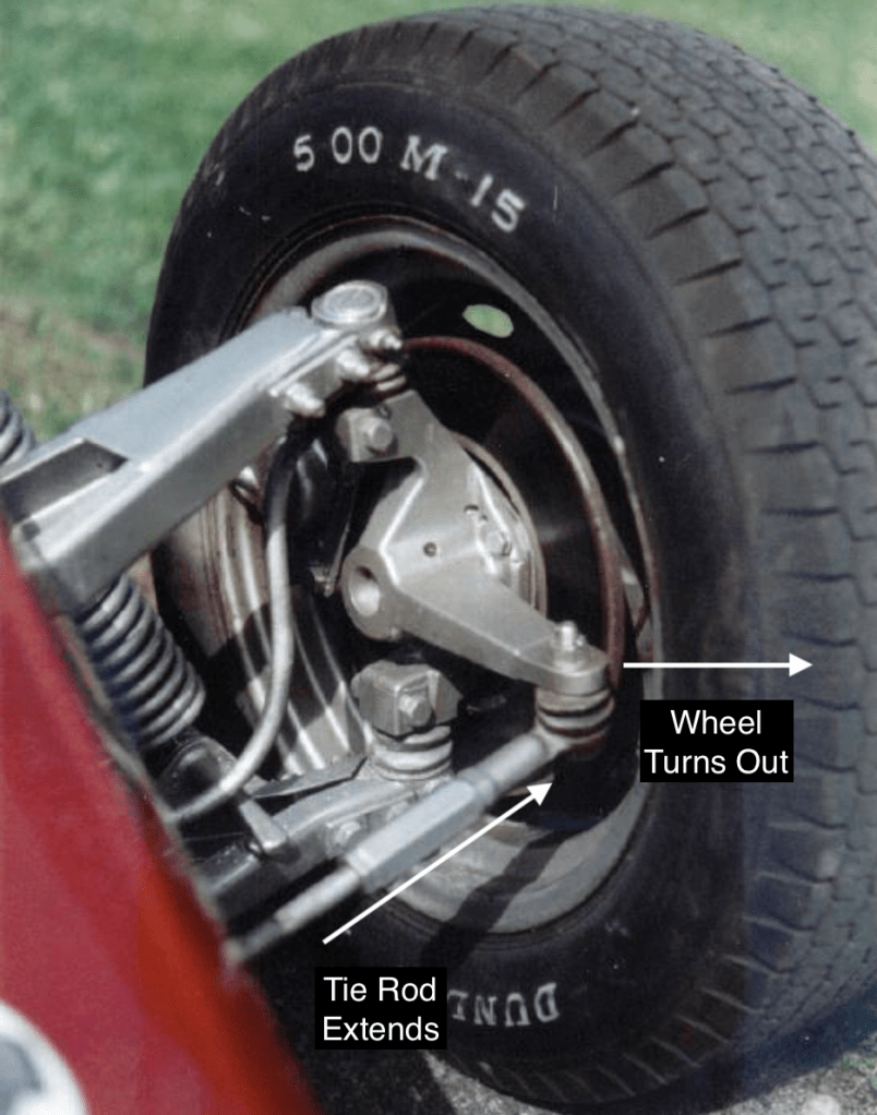
Tie Rods in Action
- You turn the steering wheel.
- The motion is transferred through the steering rack.
- The rack pushes or pulls on the inner tie rods.
- The inner rod extends or contracts, rotating the outer tie rod end.
- The outer tie rod end moves the steering knuckle, turning the front wheels.
Ball Joints:
Ball Joints allow the knuckle to move up and down with the suspension while also rotating left and right during steering. They act as pivot points between the control arms (part of the suspension) and the steering knuckle. Think of them as the “hinges” that enable smooth movement in multiple directions.
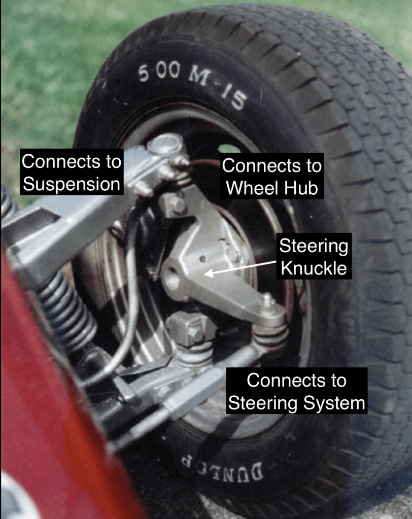
Steering Knuckle:
The steering knuckle is like the packaging puzzle piece that connects the wheel hub, suspension components and steering system together. It directly affects the Ackermann angle. The steering knuckle holds the wheel hub or spindle and rotates to steer the wheels left or right when the driver turns the steering wheel. It supports the wheel hub/bearing assembly and is attached to the suspension via control arms and ball joints. It also functions as a load transfer mechanism. It transfers vertical and lateral loads from the suspension to the wheels and vice versa.
The type of steering knuckle is based on the design of the suspension system. Either the steering knuckle is connected to the spindle or the wheel hub. Older rear wheel drive cars and trucks use the spindle type while most modern front wheel drive and all wheel drive cars use the hub type.
Step by step walkthrough:
STEP 1:
Driver turns the steering wheel and therefore turns the steering shaft
STEP 2:
Steering shaft transfers torque to intermediate shaft (if present) and U-joints
STEP 3:
Steering Gearbox or Rack and Pinion Mechanism is turned and converts rotational motion to linear motion.
STEP 4:
Steering rack moves left or right and changes the position of the tie rods and thus the wheels
STEP 5:
Tie rods either push or pull and transfer motion to knuckles
STEP 6:
Steering knuckle pivots and converts the tie rod’s push/pull into a pivot that actually turns the wheels.
STEP 7:
The wheels, mounted on the hub carried by the steering knuckle, rotate about the steering axis.
- Ackerman Steering Geometry Diagram by Dominic Byrd-McDevitt under CC BY 3.0 via Wikimedia Commons. http://en.wikipedia.org/w/index.phptitle=Image:Ackermann.jpg&redirect=no&oldid=128947145 ↩︎
- Image modified from <a href=”https://commons.wikimedia.org/wiki/File:KN13_Pulsar_SE_-_Manual_Steering_Column_Swap_03_(32899098853)_power_steering_rack.jpg”>3ndymion from US</a>, <a href=”https://creativecommons.org/licenses/by-sa/2.0″>CC BY-SA 2.0</a>, via Wikimedia Commons ↩︎
- Image modified by <a href=”https://commons.wikimedia.org/wiki/File:Steering_column.jpg”>Hundehalter</a>, <a href=”https://creativecommons.org/licenses/by-sa/3.0″>CC BY-SA 3.0</a>, via Wikimedia Commons ↩︎
- <a href=”https://commons.wikimedia.org/wiki/File:Rack_in_Century_Dictionary.png”>See page for author</a>, Public domain, via Wikimedia Commons ↩︎
- <a href=”https://commons.wikimedia.org/wiki/File:RecirculatingBall.png”>Kivaan</a>, Public domain, via Wikimedia Commons ↩︎
- Image modified from <a href=”https://commons.wikimedia.org/wiki/File:New_upper_and_lower_ball_joints,_tie_rod_ends,_boots,_shocks_and_brake_pads._(3517829024).jpg”>Craig Howell</a>, <a href=”https://creativecommons.org/licenses/by/2.0″>CC BY 2.0</a>, via Wikimedia Commons ↩︎
- Image modified from https://commons.wikimedia.org/wiki/File:Suspension.jpg#/media/File:Suspension.jpg ↩︎
- Simple Rack and Pinion System by Brian Kim Designs via ArtStation.com ↩︎
- Image modified from <a href=”https://commons.wikimedia.org/wiki/File:Tie-rod.JPG”>lemonnn</a>, Public domain, via Wikimedia Commons ↩︎

_power_steering_rack.jpg”>3ndymion)
.jpg)
Leave a comment